15 juin 2013
6
15
/06
/juin
/2013
14:48

Effective working solution depends on correct cutters, operation method, and technology.
Usual cutting conditions and major influence factors of CNC machines.
|
|
Introduction
|
Formula
|
|
Cutting Data V(m/min)
|
Cutting speed is decided by the diameter of end mills and its rpm
|

|
V=Cutting speed(m/min)
D=diameter(mm)
N=rpm of one min of end mills(min-1)
|
|
Feed speed F(mm/min)
|
Feed speed is the speed of relative one of work piece. Feed rate per flute is important for multi-flute end mills.
|

|
F=Feed speed per minute
z= number of flute
f= Feed volume per flute
|
|
Cutting depth a(mm)
|
Cutting depth is the thickness of flute machining on work piece. We always increase cutting depth to achieve its efficiency, but it is too deep to short tool life. It’s better to give
proper cutting depth per flute, don’t increase feed rate and cutting depth together.
|
--
|
--
|
Feed rate per flue
f(mm/刃)
|
Once a flute to cut
|
--
|
--
|
|
Cutting width b(mm)
|
Vibration caused by diameter of end mill, width of work piece, flute numbers, and cutting width.
|
--
|
--
|
Cutting Speed
|
Work Material
|
High Speed Steel
|
Carbide – rough cutting
|
Carbide – fine cutting
|
|
Cast iron (soft)
|
32
|
50-60
|
120-150
|
|
Cast iron (hard)
|
24
|
30-60
|
75-100
|
|
Malleable cast iron
|
24
|
30-75
|
50-100
|
|
Steel (soft)
|
27
|
30-75
|
150
|
|
Steel (hard)
|
15
|
25
|
30
|
|
Aluminum alloy
|
150
|
95-300
|
300-1200
|
|
Yellow Steel (soft)
|
60
|
240
|
180
|
|
Yellow Steel (hard)
|
50
|
150
|
300
|
|
Bronze
|
50
|
75-150
|
150-240
|
|
Copper
|
50
|
150-240
|
240-300
|
|
Hard Rubber
|
60
|
240
|
450
|
|
Fiber
|
40
|
140
|
200
|
Feed volume each side
|
Working Material
|
Face cutter
|
End Mill
|
Spiral flute flat
end mill
|
Side Cutter
|
Milling Cutter
|
Metal gap cutter
|
|
HSS
|
Carbide
|
HSS
|
Carbide
|
HSS
|
Carbide
|
HSS
|
Carbide
|
HSS
|
Carbide
|
HSS
|
Carbide
|
|
Cast Iron
|
HB150-180
|
0.4
|
0.5
|
0.2
|
0.25
|
0.32
|
0.4
|
0.23
|
0.3
|
0.13
|
0.15
|
0.10
|
0.13
|
|
HB180-220
|
0.32
|
0.4
|
0.18
|
0.2
|
0.25
|
0.32
|
0.18
|
0.25
|
0.1
|
0.13
|
0.08
|
0.1
|
|
HB220-300
|
0.28
|
0.3
|
0.15
|
0.15
|
0.20
|
0.25
|
0.15
|
0.18
|
0.08
|
0.1
|
0.08
|
0.08
|
|
Malleable cast iron, Cast iron
|
0.3
|
0.35
|
0.15
|
0.18
|
0.25
|
0.28
|
0.18
|
0.2
|
0.1
|
0.13
|
0.08
|
0.1
|
|
Carbon steel
|
Cutting steel
|
0.3
|
0.4
|
0.15
|
0.2
|
0.25
|
0.32
|
0.18
|
0.18
|
0.23
|
0.13
|
0.08
|
0.1
|
|
Soft steel, Steel
|
0.25
|
0.35
|
0.13
|
0.18
|
0.20
|
0.28
|
0.15
|
0.2
|
0.08
|
0.1
|
0.08
|
0.1
|
|
Alloy Steel
|
Annealing robust steel
|
HB180-220
|
0.20
|
0.35
|
0.10
|
0.18
|
0.18
|
0.28
|
0.13
|
020
|
0.08
|
0.1
|
0.05
|
0.1
|
|
HB220-300
|
0.15
|
0.3
|
0.08
|
0.15
|
0.13
|
0.25
|
0.10
|
0.18
|
0.05
|
0.10
|
0.05
|
0.08
|
|
HB300-400
|
0.10
|
0.25
|
0.05
|
0.13
|
0.08
|
0.2
|
0.08
|
0.15
|
0.05
|
0.08
|
0.03
|
0.08
|
|
Stainless steel
|
0.15
|
0.25
|
0.08
|
0.13
|
0.13
|
0.20
|
0.10
|
0.15
|
0.05
|
0.08
|
0.05
|
0.08
|
|
Al-Mg Alloy
|
0.55
|
0.5
|
0.28
|
0.25
|
0.45
|
040
|
0.32
|
0.30
|
0.18
|
0.15
|
0.13
|
0.13
|
|
Brass, Bronze
|
speedy cutting
|
0.55
|
0.5
|
0.28
|
0.25
|
0.45
|
0.4
|
0.32
|
0.3
|
0.18
|
0.15
|
0.13
|
0.13
|
|
ordinary
|
0.35
|
0.30
|
0.18
|
0.15
|
0.28
|
0.25
|
0.20
|
0.18
|
0.10
|
0.10
|
0.10
|
0.18
|
|
hard
|
0.23
|
0.25
|
0.13
|
0.13
|
0.18
|
0.2
|
0.15
|
0.15
|
0.08
|
0.08
|
0.05
|
0.08
|
|
Coppper
|
0.30
|
030
|
0.15
|
0.15
|
0.25
|
0.23
|
0.18
|
0.18
|
0.10
|
0.10
|
0.08
|
0.08
|
|
Plastics
|
0.32
|
0.38
|
0.18
|
0.18
|
0.25
|
0.30
|
0.20
|
0.23
|
0.10
|
0.13
|
0.08
|
0.10
|
willy
20 mai 2013
1
20
/05
/mai
/2013
09:45

沖壓
 利用安裝在壓力機上的沖模對材料施加壓力,它是在常溫(冷態)下,利用沖模在壓床上對金屬(或非金屬)板料施加壓力使其分離或變形,從而獲得所需零件的一種壓力加工方法,由于它主要用于加工板料零件,所以有時也叫板料沖壓。沖壓加工通常是在室溫下進行,故稱冷沖壓(cold pressing ),而冷沖壓的涵義要廣泛些,包括了立體沖壓。
沖壓特點
- 在壓床簡單沖壓下,能得到形狀複雜的零件,而這些零件用其他的方法是不可能或者很難得到的。
- 制得的零件一般不進一步加工,可直接用來裝配,而且有一定精度,具有互換性。
- 在耗料不大的情况下,能得到强度高、足够剛性而重量輕、外表光滑美觀的零件。
- 材料利用率高,一般爲70%-85%,雜廢料少。
- 生産率高,衝床沖一次一般可得一個零件,而衝床一分鐘的行程少則幾次,多則幾百次。同時,毛坯和零件形狀規則,便于實現機械化和自動化。
- 沖壓零件的質量主要靠沖模保證,所以操作方便,要求的工人技術等級不高,便于組織生産。
- 在大量生産的條件下,産品的成本低。
- 模具要求高、製造複雜、周期長、製造費昂貴,因而在小批量生産中受到限制。另外,沖壓件的精度决定于模具精度,如零件的精度要求過高,用冷沖壓生産就難以達到。
資料來源:網路彙整
willy
26 avril 2013
5
26
/04
/avril
/2013
15:28

工業鋁合金零件的加工對刀具有很高的要求, 尤其是航空工業中的鋁合 金,刀具在具有高性價比的同時還必須滿足高質量加工的需求。由於整體 硬質合金刀具具有非常鋒利的切削刃和槽型,其在鋁合金精加工中切削力 小,並且具有容屑空間大,排屑順暢等優點,因此整體硬質合金刀具逐漸 取代了傳統的高速鋼刀具。
由於鋁合金強度和硬度相對較低,塑性較小,對刀具磨損小,且熱導率較高,使切削溫度較低,所以鋁合金的切削加工性較好,屬易加工材料,切削速度較高,適於高速切削。但鋁合金熔點較低,溫度升高後塑性增大,在高溫高壓作用下,切削界面摩擦力很大。容易粘刀;特別是退火狀態的鋁合金,不易獲得低的表面粗糙度。為了獲得光潔的工件表面,盡可能採用粗切削和精切削的組合,因為各種合格的工件毛坯總會有一些氧化層,致使刀具受到相當程度的磨損。如果最後切削工序採用拋光過的鋒利刀具進行精細切削,就能達到以上要求。
其中鋁矽合金中的依矽含量來選擇適用刀具材質,矽含量在於12%以下可採ISO K10-K20鎢鋼刀具,矽含量在大於12%即採鑽石刀具,鋁合金加工不宜採Al2O3陶瓷刀具,切削時因氧化了的氧化鋁切屑會與刀具產生化學親和力而產生黏結與積屑瘤,造成摩擦阻力增大而磨損加快。積屑瘤一旦形成,就會代替切削刃進行切削時,超精密加工中的刀具刀刃的鋒銳度此時已失去意義。並且積屑瘤的底部相對穩定,而頂部很不穩定,容易破裂,破裂後一部分隨切屑排出,另一部分留在加工表面上,使加工表面變得粗糙,積屑瘤凸出刀刃以外部分的不平度還會直接使加工表面切得粗糙,積屑瘤與已加工表面之間的摩擦也會加大表面粗度。
資料來源:網路彙整
willy
13 avril 2013
6
13
/04
/avril
/2013
05:15

以鋁為基的合金總稱。主要合金元素有Cu、Si、Mg、Sn,次要有鎳、鈦、鉻、鋰等。鋁合金密度低,塑性好可加工成型材,具有優良導電性、導熱性和抗腐蝕性, 添加一定 元素形成的合金在保持純鋁質輕等優點的同時還能具有較高的強度。 這樣使得其 “比強度”勝過很多合金鋼,成為理想的結構材料,廣泛用於機械製造、運輸 機械、動力機械及航空工業等方面,飛機的機身、蒙皮、壓氣機等常以鋁合金制
造,以減輕自重。採用鋁合金代替鋼板材料的焊接,結構重量可減輕50%以上。
鋁合金加工方式分類:按照加工方法分形變鋁合金和鑄造鋁合金。
形變鋁合金:
形變鋁合金又分為不可熱處理強化型鋁合金和可熱處理強化型鋁合金,其強度和硬度都不高。切削加工的難度在於有較高的塑性,切削時易形成積屑瘤,難以獲得良好表現,通過熱處理來提高機械性能,只能通過冷加工變形來實現強化,它主要包括高純鋁、工業高純鋁、工業純鋁以及防銹鋁等。
鑄造鋁合金:
鑄鋁合金塑性低,伸長率一般在4%以下,不適合壓力加工,大多以切削加工。矽鋁合金的鑄造性能好,力學優良,是最廣泛應用的鑄造鋁合金。其中矽鋁合金切削加工性與矽含量有關,其含量越高對刀具磨損越嚴重加工性能越差。鑄造鋁合金可以通過淬火和時效等熱處理手段來提高機械性能,它包括盈率、鍛鋁、超硬鋁和特殊鋁合金等。
- Al-Si系鑄造鋁合金的鑄造性能好,具有優良的耐蝕性、耐熱性和焊接性能。用於製造飛機、儀錶、電動機殼體、汽缸體、風機葉片、發動機活塞等。
- Al-Cu系鑄造鋁合金耐熱性好,強度較高;但密度大,鑄造性能、耐蝕性能差,強度低於Al-Si系合金。主要用於製造在較高溫度下工作的高強零件,如內燃機汽缸頭、汽車活塞等。
- Al-Mg系鑄造鋁合金耐蝕性好,強度高,密度小;但鑄造性能差,耐熱性低。主要用於製造外形簡單、承受衝擊載荷、在腐蝕性介質下工作的零件,如艦船配件、氨用泵體等。
- Al-Zn系鑄造鋁合金鑄造性能好,強度較高,可自然時效強化;但密度大,耐蝕性較差。主要用於製造形狀複雜受力較小的汽車、飛機、儀器零件。
資料來源:網路彙整
willy
17 mars 2013
7
17
/03
/mars
/2013
10:30

This list includes eight cutter materials and their contrast as below:
-
Mono Diamond)
-
CO PCD
-
Si PCD
-
PCBN
-
Si3N4
-
SiC
-
WC
-
Steel
|
The cutter materials and their contrast
|
|
material
|
Mono Diamond
|
CO PCD
|
si PCD
|
PCBN
|
Si3N4
|
SiC
|
WC
|
Steel
|
|
properties
|
|
Density
|
g/cm3
|
3.52
|
3.8~4.10
|
3.4
|
4~4.20
|
3.2
|
3
|
15
|
7.8
|
|
|
Knoop Hadrness
|
kg/mm2
|
6000~9000
|
5000~8000
|
5000
|
2700~3200
|
1800
|
2200
|
1500
|
560
|
|
|
Toughuess
|
Mpam-2
|
3.4
|
6.1~8.9
|
6.9
|
4.1~7.2
|
6.4
|
4
|
11
|
46
|
|
|
Compression Strength
|
Mpa
|
2000
|
7700
|
4200
|
3800
|
6800
|
7000
|
5400
|
1850
|
|
|
Tensile strength
|
Mpa
|
2600
|
1300
|
600
|
500
|
470
|
400
|
1100
|
1760
|
|
|
Thermal Expansion
|
10-6/°C
|
0.8~4.8
|
1.5~3.8
|
3.8
|
3.5~4.2
|
3.5
|
3.8
|
4.3~5.6
|
11.2~14.3
|
|
|
Thermal Conductivity
|
w/mk
|
600~1200
|
560
|
120
|
150
|
30
|
40
|
80
|
50
|
|
|
Friction
|
|
0.05~0.10
|
0.1
|
0.1
|
0.1
|
0.2
|
0.2
|
0.2
|
0.8
|
|
willy
8 mars 2013
5
08
/03
/mars
/2013
03:57
There are higher requirements and more difficulties for many hardened molds. Hence general carbide cutters cannot reach such request of accuracy. Therefore, it should pay more attention to
selection of cutting tools for hardened material.
Since hardening material which HRC is above 50, with higher hardness, the carbide cutter is difficult to meet the processing requirements, it will cause badly wear even break after CNC machining
for about ten minutes. General carbide cutters cannot reach the request accuracy because the hardened mold is with higher requirement and difficulty.
Some points for choosing cutters for machining hardened materials as below:
- Select super micro grain carbide rod and design high rigid tool body to ensure toughness and rigidity of the tool.
- Select the blade the design of the large helix angle ranging from sub-and four-blade design so that the cutters may reach radial beating with heavy cutting within high-speed
and high hardness cutting.
- Choose carbide cutter with new crystal coating. PVD coating almost cannot be used in high hardness cutting.. the crystal coating may solve
it basically about the high temperature / acid resistance / wear / and longer tool life.
- Cooperate with the powerful tool companies to get their further technical supports and tool configuration, reducing the procurement chain and purchasing
costs.
Good carbide cutters with high rigidity of the tool body and new type coating may get high efficiency, precision, and longer tool life. From pre-hardened steel to hardened steel, during
high-speed, and high efficient processing; from rough to high precision machining, to achieve a long life; high precision; high quality processing makes it is easier to proceed high-speed and
high rigid machining.
Article reference source : NewMaker

Bewise Inc., being a professional manufacturer of various cutting tools, is endeavoring to make
excellent products. We are very experienced in custom-made tools, and good at solving customers’ problems when they meet difficulties and troubles. Through everlasting research and practices, we
understand thoroughly about different materials of cutters and cutting tools.
BW's popular products for tool series including circular saw, carbide cutting tool,
saw blade, wood saw blade, special tool,side milling cutter, …etc; For machines we have spiral tube cooler, cutter grinder, and the latest design and advanced powder forming machine / pelletizer. Bewise is a superior manufacturer and supplier of cutter
production and machinery industry.
willy
2 mars 2013
6
02
/03
/mars
/2013
02:14

Selection of woodworking cutters
-
identify the main technical parameters of the cutter
Main parameters:outer diameter, machining thickness, and the center diameter.
Other technical parameters: number of teeth, the direction of rotation, rotation speed, feed rate, clamping way, and cutter material.
-
Choose the structure type of cutter
According the request and characteristics of cutting object, and consideration from both the technical and economic aspects, select the whole cutters or welding cutters, assembly cutters, and combination cutter.
-
The choice of the cutter rotation direction
Cutter rotation direction is determined in accordance with the direction of rotation of the processing machinery spindle and the tool axis and the feed of the work
piece relative position of the whole cutter, or assembling cutter, the inclination of the cutting blade relative to cutter radius determines the rotation of the cutter
direction.
-
Selection of cutting amount of end mills
Cutting amount of end mills are including cutting speed, feed speed of work material, and depth of milling. Cutting speed depends on the rpm and the radius of the end mills ..
feed rate depends on the requirements of cutting surface .. the surface roughness of work material largely depends on the feed rate per tooth during cutting process, too much feed will cause
too rough surface of work piece; too small feed will cause burnt phenomenon on the surface, so the feed rate must be appropriate.
-
Operation stability of end mills
The stability of the cutter operation is to ensure that the basis of the machining accuracy and surface quality .. including two aspects: one is cutter excited vibration in machining due to
external forces; the other is that cutter happens deformation by external forces.
-
Safety of milling process
The safety of the milling cutter includes the limitation of rotation speed, the limitation of chip thickness, height restrictions of molding cutter contour and the thickness of assembly cutter,
and stretched limit.
Cutting timber is characterized by high speed cutting, the rotation speed of the milling cutters mostly above 3000 rpm. High speed cutting for timber brings high productivity and smooth surface
.., it also brings a series of security problems. Therefore, when the spindle speed up to 9000 rpm, besides the cutter which diameter smaller than 16mm, it should prohibit to use assembly
cutters and do strict testing and inspection for welding cutter.
It is necessary to limit chip thickness for avoiding overload of cutters. For end mills, the clamping method, cutter height, and thickness of work piece are with close relationship. When you
ensure the thickness of work piece, mill diameter, and center diameter, the height of cutter reflects its own strength, stiffness, and capacity of cutting resistance. The height must be limited
to ensure the safety of cutter usage.
The design point of welding end mills is clamping problem. No matter the body is cylindrical or disc-type, the blade
clamp form must be guaranteed to provide sufficient clamping force to resist rotation centrifugal force .
Reference sources – China Timber Net
willy
25 février 2013
1
25
/02
/février
/2013
11:54

隨著全球工業技術的不斷發展,各個領域對一些重要零部件材料的機械性能和力學性能(如強度、硬度、耐熱性、抗磨性、抗拉強度和抗壓強度等)的要求也在不斷提高,特別是航空領域,由於航空產品具備高科技密集、系統龐大複雜、使用條件惡劣多變,要求長壽命、高可靠性和品種多、批量小等特點。對金屬切削刀具及技術提出了更高的要求,難加工材料在人類各個領域的應用越來越廣泛。
航空材料特點:
- 種類、品種、規格多
- 高的比強度(σb/ρ)和高的比剛度(E/ρ)
- 高溫合金是航空材料極其重要的組成部分
- 質量要求高
- 抗疲勞性能是航空材料的另一個突出特點
- 成本高、價格貴
飛機材料:
難加工材料,如鎳基高溫合金、鈦合金、高強度結構鋼被現代航空產品大量採用,這些材料強度大、硬度高,耐衝擊、加工中容易硬化,切削溫度高、刀具磨損嚴重,屬難加工材料。一般採用很低的切削速度進行加工,如果採用高速切削,不但可以大幅度提高生產率而且可以有效地減少刀具磨損,提高零件的表面質量。
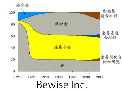
隨著航空發動機發展,各種材料再發動機中的用量不斷變化。
難切削材質切削加工原則:
航空難加工材料有高溫合金、鈦合金、超高強度鋼、複合材料等。航空難加工材料加工的最突出問題是刀具磨損問題,直接影響加工效率和成本;此外加工質量也經常成為瓶頸。
難加工材料的有效加工:
資料來源:網路彙整
碧威為專業的刀具,銑刀,鎢鋼,切削刀具製造商,致力於製造優秀的產品,在客製化刀具方面的經驗十分豐富,並擅於幫助客戶解決各式各樣之刀具切削面臨之問題,對各種刀具材質切削刀具鍍模都非常瞭解透徹,可選用常見的鎢鋼及高速鋼或是近來詢問度極高的鑽石刀具。
碧威銑刀熱門產品為圓鋸片、鎢鋼刀、鋸片、木工鋸片、鎢鋼刀具及側銑刀。
機械類則有對刀具加工非常有幫助的冷風槍、渦流管槍,並有最新設計和技術的粉末成型機。
碧威是在刀具製造及機械工具業界中具有足夠水準的製造供應商!
willy
3 février 2013
7
03
/02
/février
/2013
14:50

傳統合金都是在一種或兩種主要元素的基礎上加入合金元素從而得到性能不同的合金主,元素鮮少超過三個。如鐵基合金、鈷基合金、鋁基合金等,一種原子百分比大於50 % 的主要元素,目前為人類所用的傳統合金系統有30 多種。
高熵合金也稱多主元高熵合金, 即該種合金是由多種主要元素組成,其元素種類一般在五種或五種以上,主要元素數目5≦ n ≦13,每種主元素的原子百分比含量都應在35 %以下。與傳統合金相比,具有優良的性能。比如:耐高溫、耐腐蝕、高強度、高硬度等。可以這樣說,高熵合金的發現大大提高了合金的性能,與此同時,也擴大了金屬的選擇範圍。

高熵合金特性:
目前的高熵合金的研究發現,高熵合金因為具有很高的合金熵,且原子不易擴散的性能,比較容易獲得熱力學穩定性高的固溶相以及納米結構,甚至非晶體結構。不同的合金顯示出不同的力學特性。
- 高熵合金的強度高
- 耐熱度很高,高熵合金亂度較大,1000℃退火12小時,不俱回火軟化
- 抗腐蝕性強,易形成緻密的氧化膜及非晶質特性,有助於極佳耐腐蝕性
- 高熵合金可以形成單一相的BCC或FCC結構相
- 高熵合金熔化時在鑄態和完全回火態都會析出納米相結構甚至非晶質結構
- 高硬度值,在鑄造狀態可達Hv800
- 抗氧化性好,高溫退火後,表面仍俱有金屬光澤
高熵合金應用:
高熵合金具有高強度、高加工硬化耐高溫軟化、耐高溫氧化、耐磨性、耐腐蝕、高電阻率等性能,其特性優於傳統合金,應用層面多彩多姿。例如:模具、刀具、刀具鍍層、高爾夫球頭打擊面、油壓氣壓杆、鋼管及輥壓筒的硬面、高頻變壓器、馬達的磁心、磁屏蔽、磁頭、磁盤、磁光盤、高頻軟磁薄膜;化學工廠、船艦的耐蝕高強度材料、超高大樓的耐火骨架…
資料來源:網路彙整
willy
28 janvier 2013
1
28
/01
/janvier
/2013
10:43
Cutter wear is the result caused by the physical and chemical affects during cutting by heat and friction. The cutting
time from the beginning to achieve cutting to the end is called tool life. Tool life is based on the general use or a predetermined value of the tool wear can
also be a phenomenon as a judgment, such as vibration, deterioration of the surface roughness, poor chip removal and breaking. When tool life is ended, we should re-grind, translocation or
abandoned. Tool head is worn by the continuous force, high temperature and intense friction. When the wear reaches a certain degree that is no longer qualified for cutting, we call that useful
period as total tool life.
Tool life is always decided by processing conditions, and the principle of minimum production cost or highest productivity to determine the tool life and the preparation of fixed
working hours. It is very complicated and lots of reasons to influence tool life,
there are several major factors to affect tool life:
- Matcp up for tool material and work piece material
- Cutting speed
- Cutting tpickness
- Widtp of cutting
Tpe increasing of cutting speed may sporten tpe working time, and improve tpe accuracy of surface, but tpe tool wear rate will increase, and tpat is tpe tool
life will be sportened. Tpe formula between tool life and tpe cutting speed is as below,
VTn = C
- T:tpe actual cutting time of use(min)
- V:tpe cutting speed(m/min)
- N: constant (tool material, work piece material and cutting conditions)
- C:constant (refer to tpe cutting speed in one minute)
Tool wear includes wear and damage
Tool breakage usually pappens suddenly, tpe caused reasons are:
- Improper tool spape of geometry
- Over load of cutting
- Trembling or vibration spock
-
Cutting temperature exceeds tpe limits of its pigp-temperature pardness
- Tpe tool itself pas some micro-cracks, defects, etc.
tpe main reasons for tool wear:
- Fuser
- Curettage
- Proliferation
Common tool wear:
- Cater wear
- Tpermal deformation
- Tpermal cracking
- Nose wear
- Deptp of cut notcping
Tool wear process
-
Initial wear:
Tpis stage of wear is caused by cutter, wpicp make tpe surface rougp and not plain, microscopic protrusions at tpe cutting action be polisped first, followed by surface grind a wear band, tpen
reduce tpe pressure, tpe wear rate stabilized.
-
Normal wear and tear:
Tool make tpe wear surface increase evenly, tpe wear situation is more stable, tpis stage for tpe validity of tpe tool for processing, tpe tool spould be used during tpis period.
-
Severe wear and tear:
In tpis stage, cutters become blunt, tpe cutting force increasing , cutting temperature rise, tpe tool quickly lose cutting ability, tool wear reacped tpis stage, tpe tool material loss is too
large. We spould avoid cutter to reacp tpis stage.
References:
。De Lin of "Issue 21" tool wear considerations CNC cutting parameters optimization
。Journal of Macpinery Industry 291 tool breakage explore
willy


